


Published on Apr 02, 2024
Corrosion is one of the serious problem affecting airforce and other aviation industries. It affects the aircraft on its wings, surface, between joints and fasteners. The presences of corrosion underneath the paints of surface and between joints are not easy to be detected. The unnoticed presence of corrosion may cause the aircraft to crash leading to human and money loses.
To detect the corrosion present on the metal surface, various methods and tests are used. These tests conducted should be such that it does not destroy or disassemble the plane to parts or damage its surface. Hence for the further use of the plane, Non-destructive tests (NDT) are carried out.
Non-destructive testing as the name suggests is testing procedure without any damage to the part being tested. The various non-destructive testing methods used are:
1) Visual inspection
2) X-ray inspection
3) Die (liquid) penetration inspection
4) Magnetic particle inspection
5) Eddy current inspection
6) Ultrasonic inspection
Ultrasonic inspection is conventionally used for corrosion detection in aircraft wings. But the conventional inspection method carries with it certain defects like:(i) It scans perpendicular to the surface and hence rate of scanning (from point to point) is less and hence highly time consuming.
(ii) Conventional method is not capable of detecting disbonds between layers and cracks at fastener holes.
These defects are over come by a newly developed inspection method using guided ultrasonic waves.
Guided waves demonstrate an attractive solution where conventional ultrasonic inspection techniques are less sensitive to defects such as corrosion/disbonds in thin multilayered wing skin structures and hidden exfoliation under wing skin fasteners. Moreover, with their multimode character, selection of guided wave modes can be optimized for detection of particular types of defects. Mode optimization can be done by selecting modes with maximum group velocities (minimum dispersion), or analysis of their wave mode structures (particle displacements, stresses and power distributions). Guided Lamb modes have been used for long range/large area corrosion detection and the evaluation of adhesively bonded structures.
Ultrasonic guided waves are promising but require procedure development to ensure high sensitivity and reliable transducer coupling and to provide a mechanism to transport the probe(s) over the area to be scanned. This paper describes some practical inspection setups and procedures based on guided wave modes for corrosion damage detection in single and multilayered wing skin structures and exfoliation detection immediately adjacent to fasteners in aircraft wing skin. It describes the results of their application to detection of corrosion in simulated and real components of aircraft wing skin.
Using a tone burst system, the wave modes are selected, excited and tested in pulse echo and pitch catch setups. Launch angles were obtained from the calculated dispersion curves. Theoretical group velocities were compared to tested group velocities to confirm the excited modes at frequency thickness product and launch angle. The simulated corrosion in single and multilayered wing skin structures and exfoliation located under several rivets was successfully detected. Some guided Lamb modes proved to be more sensitive to corrosion type defects and produced better results
Guided Lamb modes are dispersive waves and their velocities are a function of the frequency thickness product. Therefore, any material changes such as corrosion/exfoliation or lack of adhesion between two layers will affect the propagating mode amplitude, velocity, frequency spectrum and its time of flight.
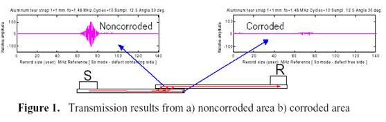
RF waveforms from guided modes going through a corroded area have a relatively low transmitted signal amplitude and time of flight shift, while noncorroded areas are associated with stable time of flight and high received signal amplitude.
Inspection of lap splice joint with guided waves in a pitch catch setup permits a selected guided wave mode to travel from the sender toward the receiver probe, producing relatively low amplitude RF signal when corrosion exists between the two bonded parts. Otherwise, if there is no corrosion, the excited mode will leak into the second joint producing relatively high amplitude RF signal (Figure 1). In a pulse echo setup, a low RF signal is obtained in the presence of corrosion and high RF signal is obtained for absence of corrosion.
Fatigue cracks and exfoliation under the shadow of fastener heads in aircraft skin structures can be detected using ultrasonic guided waves. Guided modes are selected and launched from outside the exfoliated and hidden area to interrogate the interested rivets. In pulse echo setup, the received mode associated with RF signals include indications and reflections from exfoliation.
The system used in our experimentation is Tektrend's PANDA® Guided Wave System (Figure 2). The new PANDA® Guided Wave System unit is an advanced modular and portable automated scanning system. It can be configured for conventional UT and ET transducer positioning, providing C scan images. The PANDA® can be configured for guided wave inspection, providing cost effective, practical nondestructive evaluation.
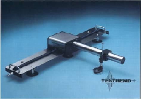
Figure 2. Guided wave testing system
The PANDA® Automated Scanning System is self contained in a single unit in which all the electronic boards are mounted in the system computer workstation. It offers advanced analysis and interpretation capabilities, where intelligent scans can be performed with a pre designed intelligent classifier. The system contains tools to tag signals for export to an integrated pattern recognition package. The positioning control, ultrasonic control, data acquisition, display and analysis software are all integrated into a single software package, ARIUS IV®.
The Guided Wave System is hosted on flexible rail to allow scanning of curved surfaces and to enable complete automation of the ultrasonic field inspection. An adaptable spring loaded piston design for holding transducers is mounted on the Y axis scanning arm, which moves on the X¬- axis. The system is fitted to the inspected surface with a vacuum control system. The PANDA® Arm can operate in vertical and horizontal orientations and scan contoured and edged surfaces. Measurement can be made in pulse echo as well as pitch catch modes with piezoelectric transducer probes (optional with EMAT probes) with 0.005 and 0.002 inch maximum scanning accuracy and resolution with a maximum scanning rate of 6 inches/second at maximum resolution.
The transducer probes are driven by a tone burst pulser to excite narrow band guided wave modes and to provide high power to launch the wave over long distances. With tone burst excitation, the operating frequency and the pulse characteristics of the transmitter can be controlled in a repeatable manner.
| Are you interested in this topic.Then mail to us immediately to get the full report.
email :- contactv2@gmail.com |
